Shop Roaster
Technician Manual
About this roaster
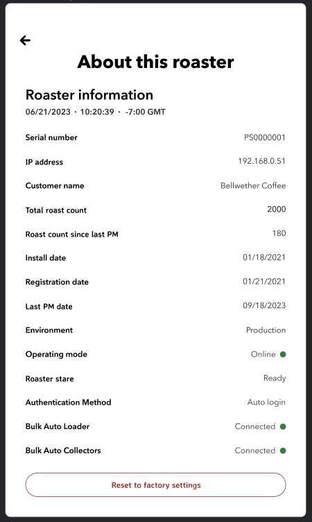
This screen displays the overall roaster information and the current state of the roaster
Serial number: The unique identifier for your roaster.
IP address: The network address assigned to your roaster for connecting to the Internet or local network.
Customer name: The registered name of the entity or individual who owns the roaster.
Total roast count: The cumulative number of roast cycles completed by the machine.
Roast count since last PM: Number of roasts since the last Preventive Maintenance (PM) was performed.
Install date: The date when the roaster was initially installed.
Registration date: The date when the roaster was registered.
Last PM date: The most recent date when Preventive Maintenance was carried out.
Environment: Indicates the operating environment, e.g., Production.
Operating mode: Shows the current operating status (e.g., Online).
Roaster state: Displays the current state of the roaster (e.g., Ready).
Authentication Method: The method used for authentication (e.g., Auto login).
Bulk Auto Loader: Indicates whether the bulk auto loader is connected and functioning properly.
Bulk Auto Collectors: Indicates whether the bulk auto collectors are connected and functioning properly.
At the bottom, there is a button labeled 'Reset to factory settings' that, when pressed, will reset the roaster's settings to their original default state as configured at the factory.
Resetting to factory setting
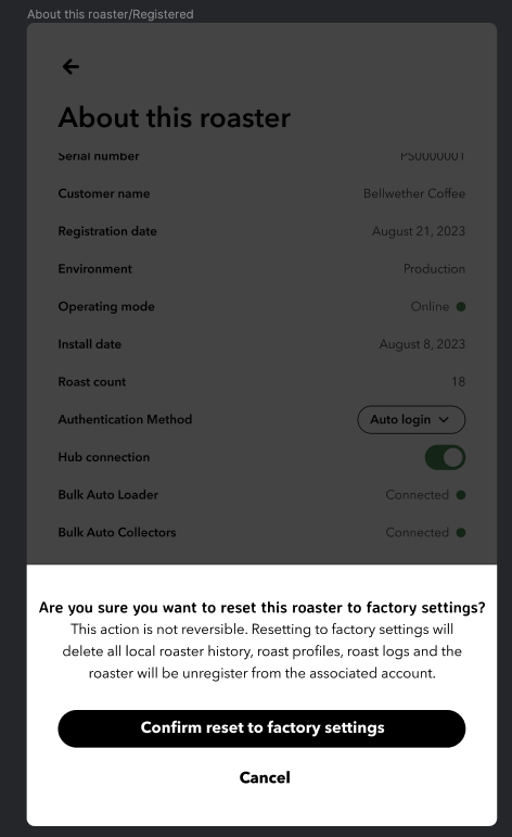
2 Factory Reset: At the bottom of the "About this Roaster” screen, there is a 'Reset to factory settings' button. When you select this button, you will be prompted to confirm your action.
1 Confirmation Prompt: A new window will appear, asking, "Are you sure you want to reset this roaster to factory settings?" It warns that this action is not reversible and that resetting to factory settings will delete all local roaster history, roast profiles, roast logs, and the roaster will be unregistered from the associated account.
2 Confirm or Cancel: If you decide to proceed, you can select 'Confirm reset to factory settings'. If you choose not to proceed, you can select 'Cancel' to return to the previous screen without making any changes.
Once the user confirms to reset the roaster to the factory setting the roaster will purge all local data and unregister the roaster. The user will be navigated to the initial screen of the roaster unboxing experience. The user can follow the unboxing instructions on the screen and re-register the roaster.
Important Notes:
Resetting the roaster to factory setting is not reversible and cannot be undone.
Before performing a factory reset, it is recommended to back up any important data associated with your roaster as this process will erase all data from the device.
Ensure that the factory reset is necessary, as it will require you to reconfigure the roaster and potentially reinstall software updates.
Maintenance and cleaning
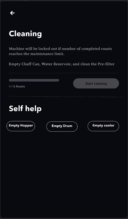
This screen is divided into three main sections: Cleaning, Self help, and Maintenance
Cleaning:
Machine Lockout Warning: A notification states that the machine will be locked out if the number of completed roasts reaches the maintenance limit. This serves as a reminder to perform regular maintenance to prevent automatic lockout.
Cleaning Instructions: Instructions are provided to empty the Chaff Can, Water Reservoir, and clean the Pre-filter, which are part of the routine cleaning procedure.
Roast Counter: A progress bar indicates the number of roasts completed since the last cleaning. In this case, it shows '0 / 6 Roasts', suggesting that no roasts have been done since the counter was last reset or since the last cleaning.
Start Cleaning Button: A button labeled 'Start cleaning' is present, which begins the cleaning cycle once pressed.
Self Help:
This section includes the following controls.
Empty Hopper: To empty all beans from the hopper.
Empty Drum: To empty the roasting drum of any remaining beans.
Empty Cooler: To clear out the bean cooler.
The 'Self Help' section is intended to assist users in performing maintenance tasks independently, without navigating through multiple menus.
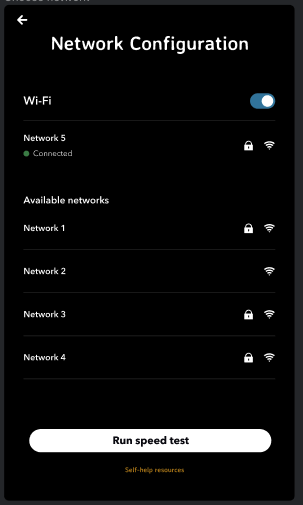
Network Configuration
This screen allows you to manage your shop roaster's Wi-Fi connections and test network speed.
Wi-Fi Toggle:
At the top, there is a switch to turn Wi-Fi on or off. When blue, Wi-Fi is enabled.
Current Connection:
Network 5: This is the network currently connected to your device. An icon indicating signal strength, and whether the network is secure or unsecure are displayed by the lock icon. Tapping on X will disconnect from the current WiFi network
Available Networks List:
Below the current connection, a list of available Wi-Fi networks is displayed (Network 1, Network 2, Network 3, Network 4), each accompanied by a signal strength indicator and, and whether the network is secure or unsecure.
Running a Speed Test:
At the bottom, there is a 'Run speed test' button that tests the internet connection speed of the connected network.
Self-Help Resources:
A link to 'Self-Help resources' is available, providing additional troubleshooting guidance or instructions for network issues.
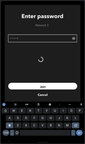
Configuring the network:
To connect to a Wi-Fi network, enable Wi-Fi and select from the available networks. Follow on-screen prompts to enter passwords if required. Enter the password for the selected network and tap on the Join button to connect to the network.
If experiencing connectivity issues, run a speed test to check the network performance or consult the 'Self-Help resources'.
Ensure your device is in an area with a strong Wi-Fi signal for reliable connectivity. Remember that network speed can affect the performance of network-dependent features on your device.
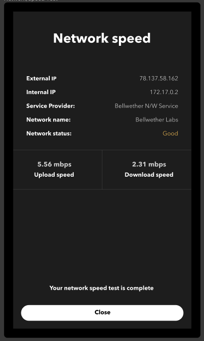
Network Speed Test
After running a network speed test on your roaster, you will be presented with a results page that provides valuable information about your network's performance.
Network Information:
External IP: This displays the public IP address through which your device is connected to the internet.
Internal IP: This shows the private IP address assigned to your device within the local network.
Service Provider: The company providing your internet service is listed here.
Network Name: The name of the Wi-Fi network you are connected to.
Network Status: A general assessment of your network condition (e.g., Good, Fair, Poor).
Speed Test Results:
Upload Speed: This is the rate at which data is sent from your device to the internet, measured in megabits per second (mbps). In this example, the upload speed is 5.56 mbps.
Download Speed: The rate at which data is downloaded from the internet to your device, also in mbps. Here, the download speed is 2.31 mbps.
Understanding the network speed test results
Interpreting Results:
- Higher numbers in both upload and download speeds generally indicate better network performance.
- Upload speed is crucial for various tasks performed by the roaster like service authentications, uploading log files to the cloud, syncing roast data with the backend services etc…
- Download speed is important for downloading roast profiles, downloading software updates etc...
Completion:
Once you have reviewed the results, press the 'Close' button to exit the Network Speed Test Results page.
If Your Speeds Are Slower Than Expected:
- Restart your router and rerun the test.
- Check for any issues with your service provider.
- Ensure no other devices are using the network heavily at the same time.
- If problems persist, contact your internet service provider or refer to the 'Self-Help resources' for troubleshooting steps.
Remember that network speeds can vary based on several factors, including your internet plan, network traffic, and the capabilities of your network device.
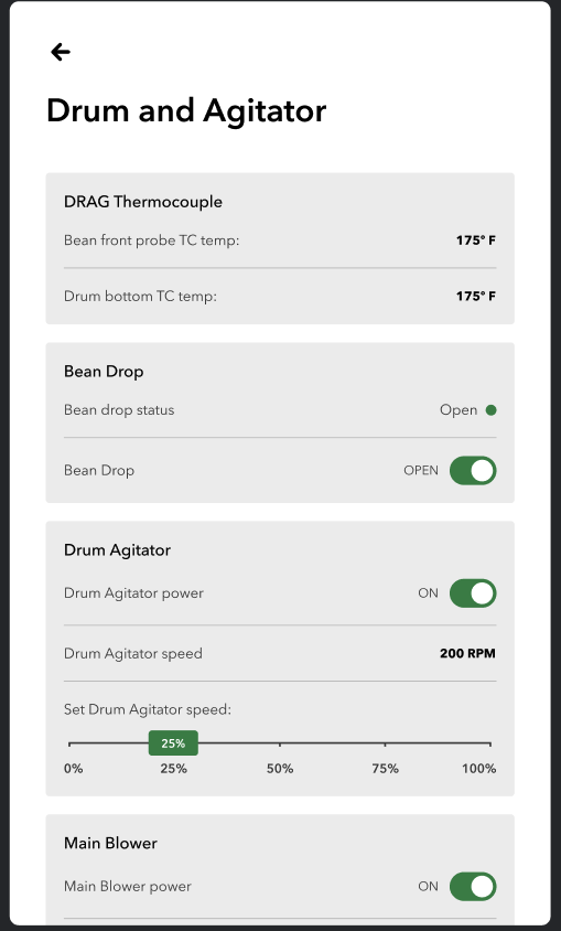
Drum and Agitator (DRAG) Control Panel
This section of your coffee roaster's interface allows you to monitor and control the functionalities related to drum and agitator.
DRAG Thermocouple:
Bean probe TC temp: Shows the temperature of the beans, currently at 175°F.
Drum bottom TC temp: Displays the temperature at the bottom of the drum, which is also at 175°F.
Bean Drop Control:
Bean drop status: Indicates whether the bean drop is open or closed. The current status is 'Open'.
Bean Drop Toggle: You can open or close the bean drop by toggling this switch.
Use the bean drop to introduce beans into the drum or to cease the flow when the desired amount of beans has been loaded.
Drum Agitator:
Drum Agitator power: Toggle this switch to turn the drum agitator on or off. It is currently 'On'.
Drum Agitator speed: This displays the current agitator speed, which is set at 200 RPM.
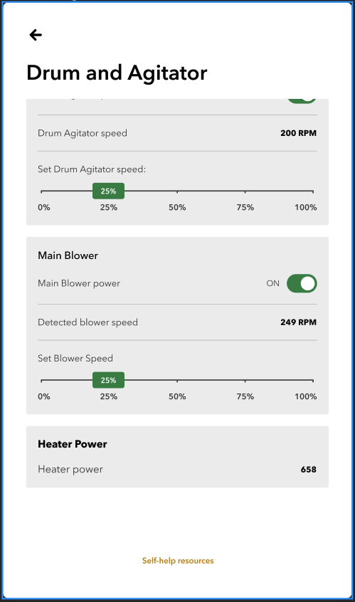
Adjust the agitator speed by using the sliding scale below. Set the desired speed by moving the slider to the appropriate position between 0% and 100%.
Main Blower:
Main Blower power: Use this button to control the power to the main blower. It is currently 'On'.
Detected blower speed: Shows the current speed of the blower, at 249 RPM.
Similar to the drum agitator, adjust the blower speed using the sliding scale. Slide to the desired level to test the consistent airflow through the roasting drum.
Heater Power:
Heater power: This numeric value indicates the current power level of the heater, displayed as 658.
Self-Help Resources:
For additional guidance or troubleshooting, use the 'Self-help resources' link provided.

Bean Cooling and Collection Control Panel
This control panel allows you to interface with the control essential for the cooling of the beans after roasting, as well as their subsequent collection.
Bean Cooler Thermocouple:
Bean Cooler TC Temp: Displays the current temperature of the beans inside the bean cooler. The temperature reading is vital for ensuring the beans are cooled to the desired level. Currently, it shows a temperature of 175°F.
Bean Cooler:
Bean Cooler Status: Indicates if the bean cooler is properly detected by the system, which should show 'Detected'.
Bean Cooler Lock: Use this toggle to secure the bean cooler during operation. It should be set to 'On' to prevent the cooler from being disengaged during the cooling process.
The cooler must be locked in place to ensure safety and proper function.
Bean Cooling Blower:
Cooling Blower Power: Controls the operational state of the cooling blower. Switch to 'On' to activate the blower for bean cooling. Toggle the switch to ‘Off’
Detected Blower Speed: Indicates the current operational speed of the blower, which is 249 RPM in this instance.
Set Blower Speed: Adjust the speed of the blower by sliding the control. Position it between 0% to 100% based on the cooling requirement for your beans.
Proper operation and control of the blower speed is crucial for efficient bean cooling.
Continuous Roasting Bean Cooler:
Continuous Roasting Bean Cooler: This shows whether the system has detected the continuous roasting bean cooler, which should be 'Detected'.
Bean Exit Status: Displays the status of the bean exit gate. It allows beans to transfer from bean cooler to the bean collector. 'Ready' state indicates that bean exit is functional and properly homed.
Bean Exit Control: Operates the gate that allows beans to exit the cooler. It's currently 'Closed'. Open it to allow the beans to exit the cooler when they are ready.
Ensure the exit gate is managed correctly to transition beans to the collection phase without compromising their quality.
Bean Collector:
Bean Collector Status: This shows whether the bean collector is detected by the system, which should read 'Detected'.
The bean collector must be detected for the beans to be properly gathered after cooling.
Chaff and Water Collector:
Chaff and Water Collector Status: Indicates if the chaff and water collector is detected, which is essential for the removal of by-products from the roasting process. It currently reads 'Detected'.
Check the chaff and water collector regularly to maintain cleanliness and efficiency.
Self-Help Resources:
For additional assistance or troubleshooting, refer to the 'Self-help resources' link provided on the interface.
Thermocouple Status Screen
Overview
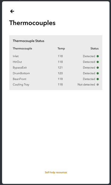
The "Thermocouples" screen displays the current temperature readings and detection status of various thermocouples within the system. This screen is essential for monitoring the operational status and ensuring the system is functioning correctly.
Screen Layout
Thermocouple: Lists the name of each thermocouple sensor within the system.
Temp: Displays the current temperature reading of each thermocouple in degrees Celsius.
Status: Indicates whether each thermocouple is actively detected by the system. A green dot signifies an active detection, while a gray dot indicates that the thermocouple is not detected.
Instructions for Use
- Viewing Temperature Data:
- Browse through the list to view the temperature readings of the different thermocouples.
- Ensure that all critical components such as the Inlet, HtrOut, BypassExit, DrumBottom, and BeanFront show the 'Detected' status for optimal operation.
Identifying Issues:
Check for any thermocouples labeled as 'Not detected'. This indicates a potential issue with the sensor or the connection that needs further investigation.
If a thermocouple is not detected, consult the troubleshooting section or contact support for assistance.
Refresh Data:
If the information appears outdated or if you suspect a malfunction, refresh the data (if applicable, depending on the system setup) to verify the current status of the sensors.
Accessing Further Resources:
Click on 'Self-help resources' to access troubleshooting guides, FAQs, and contact information for technical support.
Troubleshooting
If any thermocouple consistently shows unusual temperatures or fails to be detected, follow these steps:
Ensure that all connections to the thermocouple are secure.
Verify that there is no physical damage to the sensor.
Restart the system to reset the sensor connections.
If problems persist after these steps, refer to the detailed troubleshooting guide in the 'Self-help resources' or contact technical support for further assistance.
This screen is an essential tool for maintaining the effective operation of your system. Regular monitoring and prompt attention to any discrepancies in the thermocouple readings are crucial for preventing operational disruptions.
Bypass Controls Screen
Overview
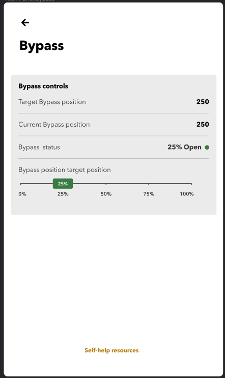
The "Bypass" screen allows users to monitor and adjust the position of the bypass valve in the system. This feature is critical for controlling the flow rate or diverting the air flow within the system.
Screen Layout
- Target Bypass Position: Displays the desired position setting for the bypass as a numerical value.
- Current Bypass Position: Shows the current position of the bypass as a numerical value, indicating how closely the actual position matches the target.
- Bypass Status: Indicates the percentage the bypass is open, providing a quick visual reference on the operation status.
- Bypass Position Target Slider: Allows users to adjust the target bypass position by sliding between 0% (fully closed) and 100% (fully open).
Instructions for Use
Monitoring Bypass Status:
- Review the "Current Bypass Position" and "Target Bypass Position" to ensure they match. If there is a discrepancy, further adjustment might be necessary.
- Observe the "Bypass Status" to quickly understand how much the bypass is currently open.
Adjusting the Bypass:
- To change the target position, use the slider under "Bypass Position Target Position". Slide to the desired percentage, which automatically updates the "Target Bypass Position".
- The system should automatically adjust the bypass to match the new target. Confirm that the "Current Bypass Position" updates to reflect this change after a short delay.
Operational Tips:
- For precise control, adjustments should be made incrementally, especially in systems sensitive to flow rate changes.
- Monitor the system’s response to each adjustment to ensure optimal operation.
- Accessing Further Resources:
- Click on 'Self-help resources' to access troubleshooting guides, FAQs, and contact information for technical support.
Troubleshooting
- Bypass Not Adjusting: If the "Current Bypass Position" does not update after setting a new target:
- Check for any mechanical obstructions or issues in the bypass mechanism.
- Ensure that the control system is receiving power and that all connections are secure.
- If the issue persists, consult the troubleshooting section in the 'Self-help resources' or contact technical support for assistance.
Safety Precautions
- Always ensure the system is in a safe state before making adjustments.
- Avoid rapid changes in the bypass settings which may lead to system instability or mechanical stress.