
Instructions for converting the Shop Roaster to support continuous roasting
Instructions for converting the Shop Roaster to support continuous roasting
Converting the Shop Roaster to support continuous roasting involves following three steps
- Installing the Autoloader unit
- Installing the modified Bean Cooler and
- Installing the Bean Collector unit
-
Installing the Autoloader unit
Locate the autoloader unit. The schematic of the autolader is as shown in the diagram below.
Locate the Autoloader controller PCB near the motor in the Autoloader unit.
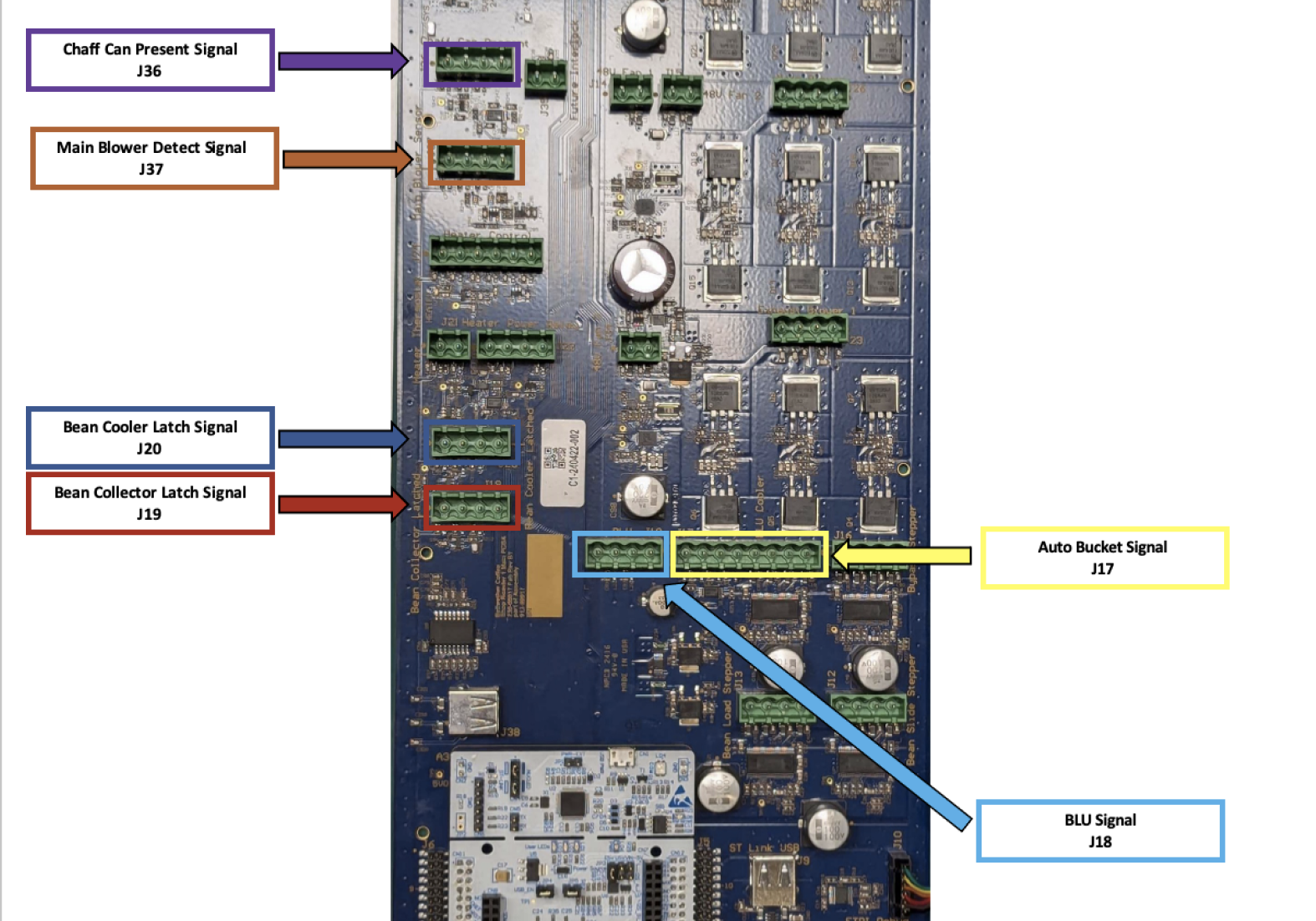
Connect the cable from Jumper J1 on the autoloader controller PCB to connector J18 [highlighted with light blue] on the Shop Roaster PCB.
-
Installing the modified bean cooler for continuous roasting
The schematic diagram for the modified bean cooler to support continuous roasting is as display below
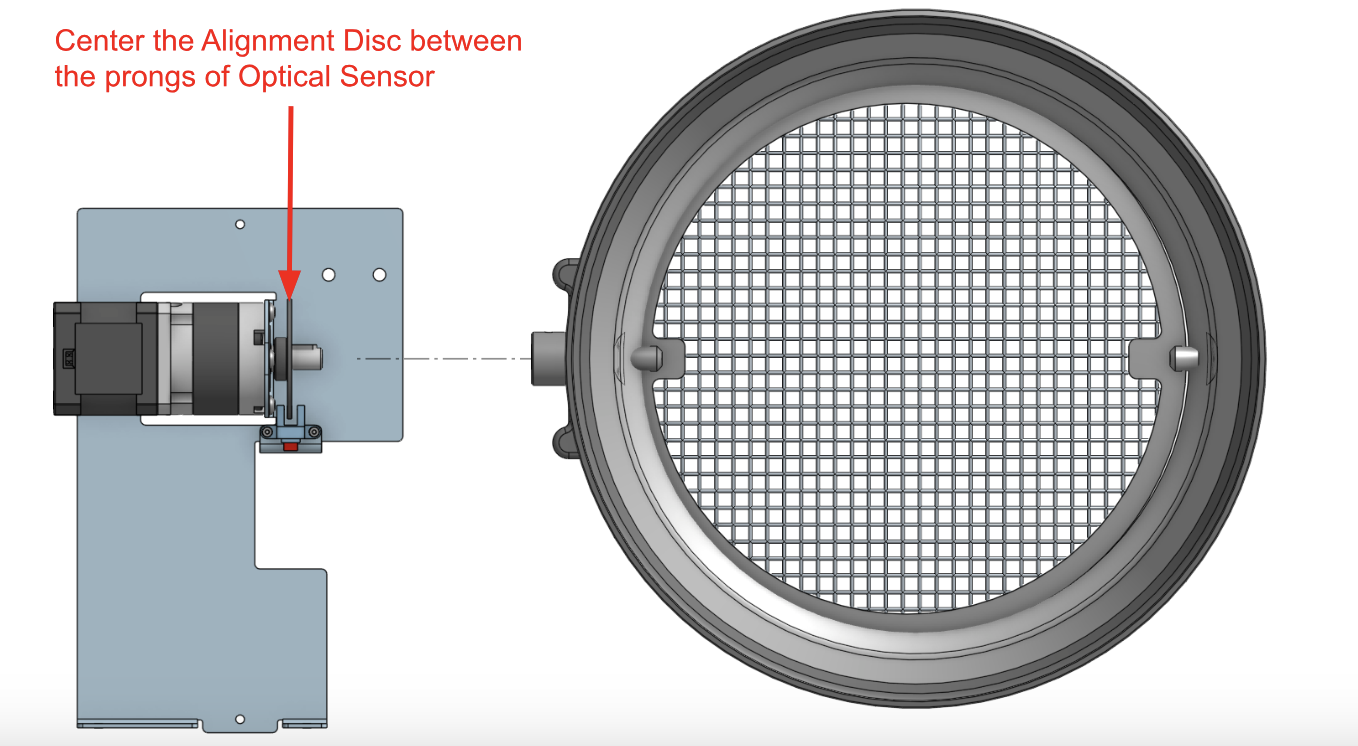
Locate the cable to connector the motor and home sensor to the main PCB of the Shop Roaster as illustrated below
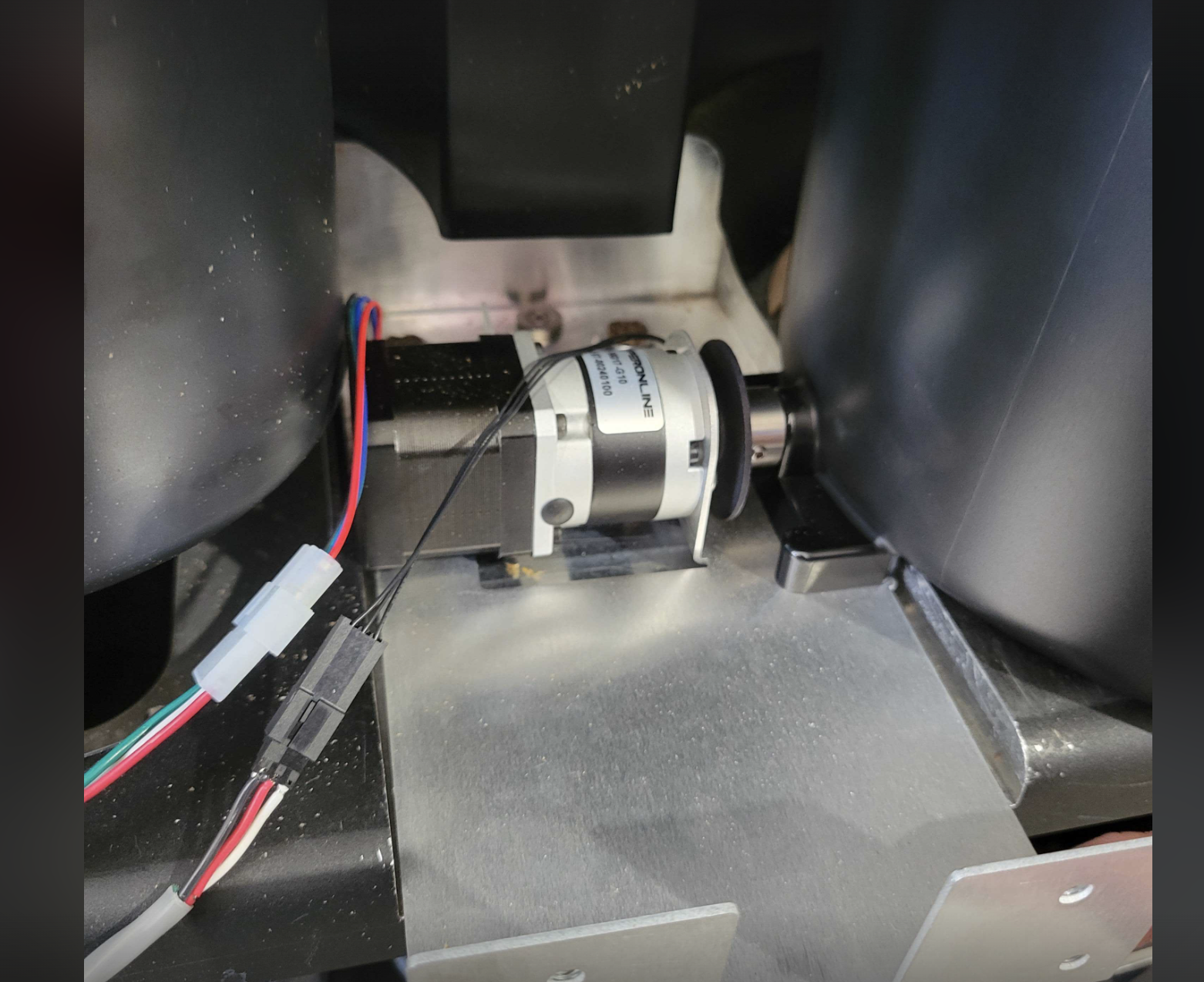
Route the cable through the black channel behind the motor and connect the green connector of the cable to J17 connector [highlighted in yellow] on the main PCB of the Shop Roaster.
-
Installing the Bean collector unit for continuous roasting
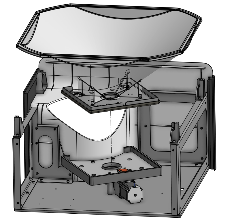
Locate the bean collector unit. The unit comes pre assembled and looks as displayed in the figure below.
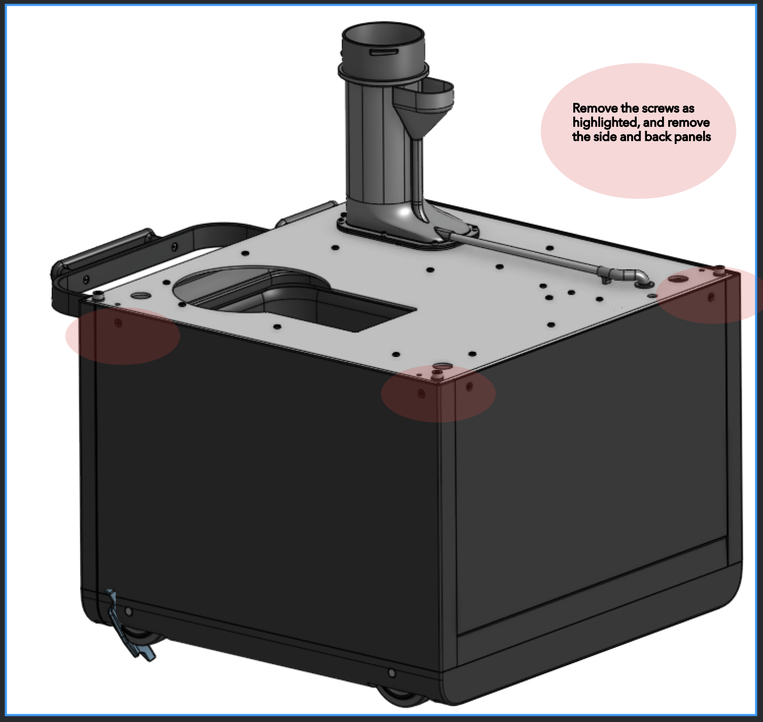
Remove the screws from the side panel and back panel as highlighted. And remove the side and back panels.
The bean collector unit will resemble as illustrated after removing the back and side panels
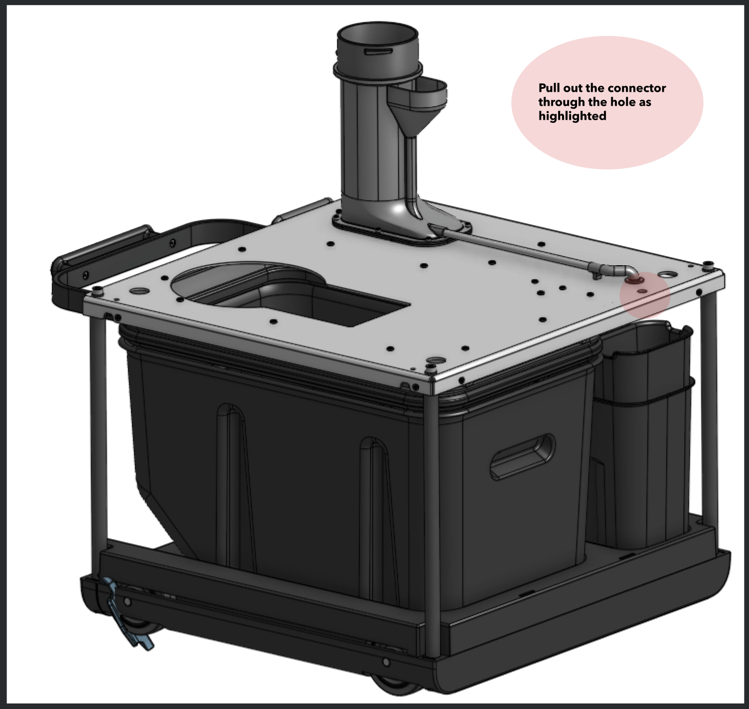
You will notice a cable with two black connectors folded near the chaff can. Pull out the connectors from the hole as highlighted in the above figure.
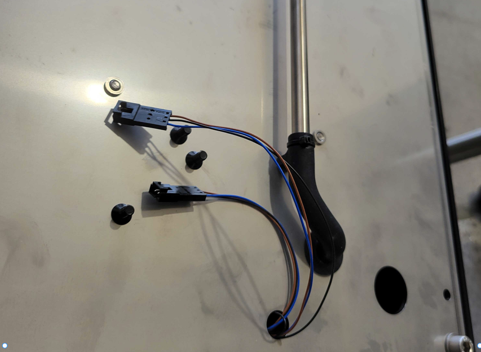
After you route the connector the unit will resemble as below.
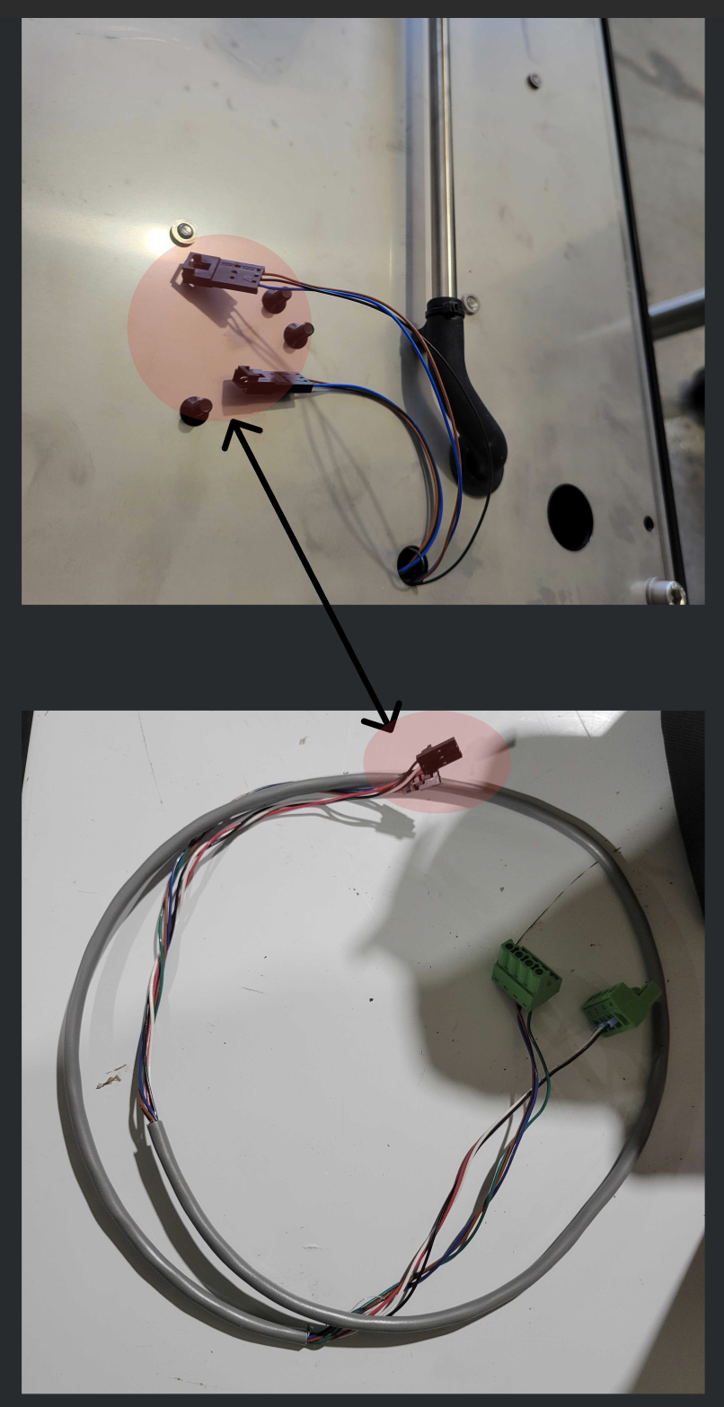
Locate the provided cable to connect the bean collector unit to the main Shop Roaster PCB.
This cable looks as illustrated in the figure below.
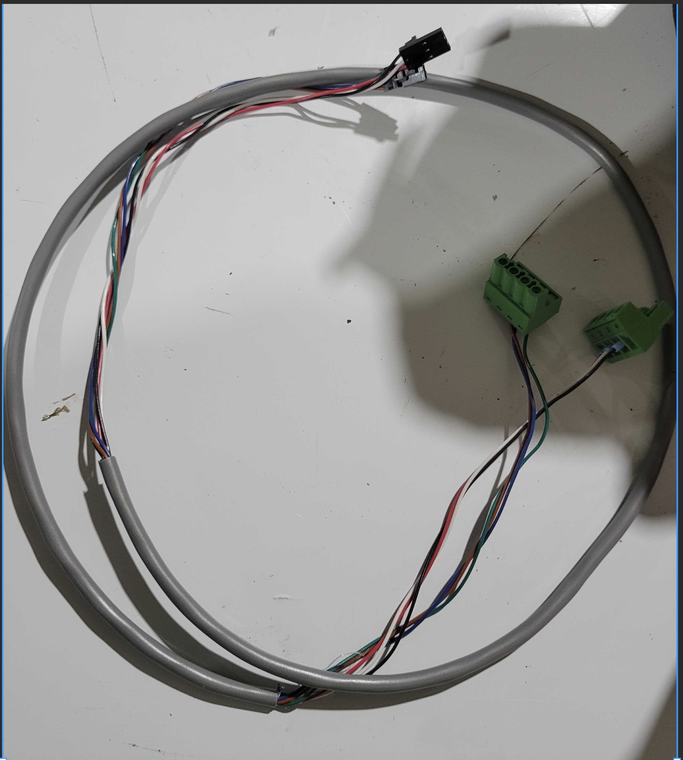
Connect the black connector from the bean collector cable to the black connector of the adapter cable as illustrated in the following figure.
Remove the skins from the roasters and the main PCB board is located on the left side of the Shop Roaster.
Connect the green connector from adapter cable for Bean Collector Latch to the J19 connector on the PCB.
Connect the green connector from the adapter cable for the chaff can detect to the J36 connector on the PCB.
This completes the connecting the bean collector unit for continuous roasting to the Shop Roaster.